filmov
tv
design the combinational circuit defined by the following three Boolean functions:
0:21:40
Boolean Function Representation: SOP and POS Form | Minterms and Maxterms Explained
0:04:44
Implementation using 3 to 8 Decoder | Logic Circuit
0:00:51
simplify boolean function using k-map
0:00:16
This chapter closes now, for the next one to begin. 🥂✨.#iitbombay #convocation
0:00:15
Cosplay by b.tech final year at IIT Kharagpur
0:00:11
IIT Bombay CSE 😍 #shorts #iit #iitbombay
0:06:36
Stick diagram of a Boolean function || Explore the way
0:00:36
Digital Logic Design - Design a 3 Input Square Circuit Using Logic Gates & Simplified Bool Functions
0:09:35
Constructing Truth Tables for Combinational Logic Circuits
0:00:05
Basics of LOGIC GATES in DIGITAL ELECTRONICS💡 #shorts #electrical #electronics #digitalelectronics
0:04:44
Lec 11: K-Map Minimization Explained | Introduction to Karnaugh Map | Digital Electronics
0:10:03
Example Problems Boolean Expression Simplification
0:00:52
Find Boolean Expression From Logic Circuit
0:21:38
Logic Gates | Boolean Algebra | Types of Logic Gates | AND, OR, NOT, NOR, NAND
0:10:07
Implement the given function using 4:1 multiplexer. 𝑭(𝑨,𝑩,𝑪)=∑(𝟏,𝟑,𝟓,𝟔)
0:07:13
Implementation of Boolean Function using Multiplexers || 8:1 || 4:1 || implementing boolean function
0:00:49
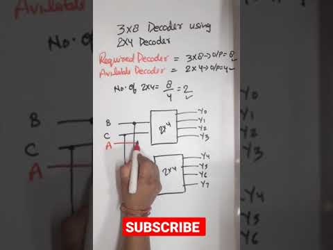
Design 3 to 8 line decoder using 2 to 4 line decoder
0:02:22
End Ch Q 4.4 || Design a Combinational Circuit with Three Inputs || Moris Mano
0:08:49
Programmable Logic Array (PLA) in Digital Electronics || DLD | Implement Boolean functions using PLA
0:05:50
4 variable kmap(karnaugh map) || IN TELUGU || DIGITAL ELECTRONICS || ECET,BTECH, DIPLOMA
0:01:58
Writing a Logic Expression From a Truth Table: 3 Inputs
0:05:47
Implementation of Boolean Expression using CMOS | S Vijay Murugan
0:14:20
Half Adder and Full Adder Explained | The Full Adder using Half Adder
Назад
Вперёд
 0:21:40
 0:04:44
 0:00:51
 0:00:16
 0:00:15
 0:00:11
 0:06:36
 0:00:36
 0:09:35
 0:00:05
 0:04:44
 0:10:03
 0:00:52
 0:21:38
 0:10:07
 0:07:13
 0:00:49
 0:02:22
 0:08:49
 0:05:50
 0:01:58
 0:05:47
 0:14:20